Monday, June 5, 2023

stm32g030 read analog PA0 and PA3 code with STM32CubeID


To read analog values from pins PA0 and PA3 on the STM32G030 microcontroller using STM32CubeIDE, you can follow these steps:

  1. Open STM32CubeIDE and create a new project.

  2. Select the appropriate board or microcontroller model (STM32G030 in this case).

  3. Configure the necessary settings for your project, such as clock configuration and GPIO pins.

  4. Enable the ADC peripheral:

    • Go to the "Pinout & Configuration" tab.
    • Select the desired ADC channel(s) for PA0 and PA3 by clicking on the respective pins.
    • Assign the pins to the ADC peripheral.
    • Click on the "ADC" peripheral in the "Middlewares" section.
    • Enable the ADC and configure its settings, such as resolution, sampling time, and conversion mode.
  5. In your code, include the necessary header files:

#include "stm32g0xx_hal.h"

1. Initialize the ADC and GPIO:

ADC_HandleTypeDef hadc;
GPIO_InitTypeDef GPIO_InitStruct;

void SystemClock_Config(void);
void Error_Handler(void);

void MX_GPIO_Init(void)
{
  /* GPIO Ports Clock Enable */
  __HAL_RCC_GPIOA_CLK_ENABLE();

  /*Configure GPIO pin : PA0 */
  GPIO_InitStruct.Pin = GPIO_PIN_0;
  GPIO_InitStruct.Mode = GPIO_MODE_ANALOG;
  GPIO_InitStruct.Pull = GPIO_NOPULL;
  HAL_GPIO_Init(GPIOA, &GPIO_InitStruct);

  /*Configure GPIO pin : PA3 */
  GPIO_InitStruct.Pin = GPIO_PIN_3;
  GPIO_InitStruct.Mode = GPIO_MODE_ANALOG;
  GPIO_InitStruct.Pull = GPIO_NOPULL;
  HAL_GPIO_Init(GPIOA, &GPIO_InitStruct);
}

void MX_ADC_Init(void)
{
  ADC_ChannelConfTypeDef sConfig;

  /* ADC Initialization */
  hadc.Instance = ADC1;
  hadc.Init.ClockPrescaler = ADC_CLOCK_ASYNC_DIV1;
  hadc.Init.Resolution = ADC_RESOLUTION_12B;
  hadc.Init.DataAlign = ADC_DATAALIGN_RIGHT;
  hadc.Init.ScanConvMode = ADC_SCAN_DISABLE;
  hadc.Init.EOCSelection = ADC_EOC_SINGLE_CONV;
  hadc.Init.LowPowerAutoWait = DISABLE;
  hadc.Init.LowPowerAutoPowerOff = DISABLE;
  hadc.Init.ContinuousConvMode = DISABLE;
  hadc.Init.DiscontinuousConvMode = DISABLE;
  hadc.Init.ExternalTrigConv = ADC_SOFTWARE_START;
  hadc.Init.ExternalTrigConvEdge = ADC_EXTERNALTRIGCONVEDGE_NONE;
  hadc.Init.DMAContinuousRequests = DISABLE;
  hadc.Init.Overrun = ADC_OVR_DATA_OVERWRITTEN;
  if (HAL_ADC_Init(&hadc) != HAL_OK)
  {
    Error_Handler();
  }

  /* Configure ADC channel */
  sConfig.Channel = ADC_CHANNEL_0; // PA0
  sConfig.Rank = 1;
  sConfig.SamplingTime = ADC_SAMPLETIME_13CYCLES_5;
  sConfig.SingleDiff = ADC_SINGLE_ENDED;
  sConfig.OffsetNumber = ADC_OFFSET_NONE;
  sConfig.Offset = 0;
  if (HAL_ADC_ConfigChannel(&hadc, &sConfig) != HAL_OK)
  {
    Error_Handler();
  }

  sConfig.Channel = ADC_CHANNEL_3; // PA3
  sConfig.Rank = 2;
if (HAL_ADC_ConfigChannel(&hadc, &sConfig) != HAL_OK) { Error_Handler(); } } int main(void) { /* MCU Configuration */ HAL_Init(); SystemClock_Config(); /* Initialize GPIOs and ADC */ MX_GPIO_Init(); MX_ADC_Init(); /* Infinite loop */ while (1) { /* Start ADC conversion */ if (HAL_ADC_Start(&hadc) != HAL_OK) { Error_Handler(); } /* Wait for conversion to complete */ if (HAL_ADC_PollForConversion(&hadc, HAL_MAX_DELAY) != HAL_OK) { Error_Handler(); } /* Read the converted value */ uint32_t adcValue = HAL_ADC_GetValue(&hadc); /* Do something with the ADC value */ // ... /* Stop ADC conversion */ if (HAL_ADC_Stop(&hadc) != HAL_OK) { Error_Handler(); } } }

Make sure to handle any errors appropriately in the Error_Handler() function.

1. Build and flash your project to the STM32G030 microcontroller.

This code initializes the ADC peripheral and sets up PA0 and PA3 as analog inputs. Inside the infinite loop, it starts an ADC conversion, waits for it to complete, retrieves the converted value, and then stops the ADC conversion. You can perform any necessary processing or actions with the ADC value as required.

Remember to refer to the STM32G0 HAL reference manual and the STM32CubeG0 firmware package documentation for more details on the ADC and GPIO APIs and configurations specific to your needs.

Continue Reading →

Thursday, February 4, 2021

Tuesday, November 10, 2020

Amazing Home automation system with STM32F103 microcontroller Part 1

Amazing Home automation system with STM32F103 microcontroller

Visit my Youtube channnels :  Electro_Magic ; Practical Tips  ; Delphi practical school             


Amazing Home automation


This is ongoing project of building Home automation system ( smart home system ), which will for the start have measurement of temperature and humidity.

It will consist of number of parts ( number of blog posts ).

It is planed to work with micro controller STM32F103C8T6


STM32F103C8T6 microcontroller


 and 3.5" TFT LCD.


3.5" TFT LCD


Next step will be to control relays for ceiling fan, etc.

Next will be to add ESP8266 to have connection to the internet, so the system can be controlled remotely.

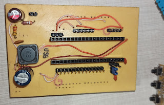
Till now I have managed to make a printed circuit board.


Home automation board
Home automation board bottom


Home automation board
Home automation board top


Not really nice to look at, but it is working, and working from the first attempt :-)

The PCB is designed in EasyEDA, and made with toner transfer method 


Except headers for STM32 and TFT LCD, I have also added 3.3V and 5.0V linear regulators.
Beside this, there is also part with MC34063 as a buck converter, which is in front of small linear regulators.
This part is made with intention to connect this device to external power source of 12V.


Of course, everything is programmed using Arduino IDE and STM32duino board.

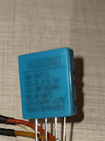
For measuring temperature and humidity we use DHT11 sensor, which measures temperature and also humidity and uses just three wires, plus, ground and signal.

DHT11 sensor


Continue Reading →

Friday, October 23, 2020

DIY method of making PCB using toner transfer method


This is a DIY method of making PCB using toner transfer method. 

Visit my Youtube channnels :  Electro_Magic ; Practical Tips  ; Delphi practical school             


The most important thing is to have good print , done with good quality toner. 
Here we use some dangerous chemicals so be very careful if you going to do this at home.
Please check following video for details, and I will show you also few steps in following points.


As a first step we use sandpaper to remove any oxidation from copper plate, than clean it with paper tissue.


PCB Board

Than we use contact cleaner or acetone to clean any grease.

Contact Cleaner

Then we secure the paper with printed circuit with adhesive tape.

paper with printed circuit

Then  we use nail polish remover ( or acetone - nail polish remover is actually acetone ), take small amount and spread it evenly on the surface of the copper plate.

nail polish remover

nail polish remover

Ten minutes after we can start to remove paper very slowly.

DIY PCB

After we removed first layer of paper we put board into the water, and slowly rubbing we remove the rest of the paper.
This rubbing should be done VERY carefully, so we do not damage toner traces.

DIY PCB

And in the end , the result is very satisfactory.

DIY PCB

Next step will be to do the etching, which could be done with HCL and hydrogen peroxide.


Continue Reading →

Thursday, August 20, 2020

Etching PCB with HCL and hydrogen peroxide

This is a DIY method of making PCB using HCL  and hydrogen peroxide .

Visit my Youtube channnels :  Electro_Magic ; Practical Tips  ; Delphi practical school             

The most important thing is to have good print , done with good quality toner. 
 Here we use some dangerous chemicals so be very careful if you going to do this at home.
Please check following video for details, and I will show you also few steps in following points.


First you must have good print, done with good quality toner.

Printed circuit board

      Then we put prepared PCB in plastic box.
Chemicals

For etching we use HCL and Hydrogen peroxide.We pour in HCL just enough to cover PCB, then we add a little of peroxide.
HCL

Hydrogen peroxide


We immediately see how reactions with copper occur.


Here we see bubbles in the reaction of acid with copper.


After few minutes we can see full reaction .


After etching is done, we rinse pcb with water.


Use a steel sponge to remove any toner residue.


The PCB looks almost perfect.


It is very important to have a well-done print at the very beginning, with quality toner.


Continue Reading →

Monday, April 9, 2018

Compress files and folders to zip file with Delphi (Tip for 10 )


Visit my Youtube channnels :  Electro_Magic ; Practical Tips  ; Delphi practical school             

This is an example of zipping ( compressing ) files and folders with Delphi using "FWZip" component which can be downloaded from following link :


https://github.com/AlexanderBagel/FWZip

In this video you can see full procedure of this example :


And following is full source of this example :


Continue Reading →

Wednesday, January 3, 2018

Export Image To PDF with Delphi (Tip for 10 )


Visit my Youtube channnels :  Electro_Magic ; Practical Tips  ; Delphi practical school

This is example how one can export image from Delphi application to PDF file, using open source library SynPDF.


In the following video full procedure is described


Library can be downloaded from :
https://github.com/synopse/SynPDF

Following is full source code :
Edited 10.01.2018 : added code for the Form after main code.
Continue Reading →

Wednesday, December 13, 2017

Thursday, November 30, 2017

LAB power supply with current control (Tip for 10 )

LAB power supply with current control from 0 to 1.5 Ampere (Tip for 10 )


This is simpler version of variable power supply shown in this post.

Voltage is variable from 0 to 30 Volts and current from 0 to 1.5 Ampere.

LM317T is mostly in standard setup.

Potentiometer for voltage control is connected to ADJ pin of LM317T and negative voltage via trim pot, with which you can adjust minimum voltage.

Current control is done using  LM393 comparator and shunt resistror.

Output of LM393 is connected to ADJ pin of LM317T and regulates amperage, sensed over shunt resistor.


Continue Reading →

Wednesday, November 29, 2017

Get Base File Info (Tip for 10 )


Here you can see example of getting basic file information.

Complete procedure of making this example program can be seen in the following video.


And following is full source code that you can use to test this example by yourself.


Continue Reading →

LM317 Variable power supply with current control (Tip for 10 )


In this post I will show you easy to construct variable power supply using LM317 with some other components.

Final result is usable variable lab power supply with current control.

Current control is done using  LM393 comparator and shunt resistror.

Since I used one panel meter for voltage and current reading , I added LM358 OP amp to read current used by attached loads.

LM358 amplifies voltage detected on shunt resistor and amplify it to appropriate value which is set by variable trim pot.


Continue Reading →

Monday, October 30, 2017

Get Computer Drives - Delphi Tutorial (Tip for 10 )


In this example you can see how we can get list of Computer Drives with icons and labels.

 First, check this video with details for this example .


 And of course following is the source code of this example :

Continue Reading →

Friday, October 13, 2017

Web browser Delphi Example (Tip for 10 )


As you will see, it is possible to create simple Web browser very quickly using Delphi and component TWebBrowser , which encapsulates Internet Explorer ActiveX component.

In this video you can see all the details of creating such web browser :

And of course following is the source code for this example :

Continue Reading →

Popular Posts

Recent Posts

Unordered List

Text Widget

Pages

Search This Blog

Powered by Blogger.

Contributors

Text Widget